Earthfault:
Earthfault
detection in insulated medium-voltage network must be designed
properly. Two methods may be used to detect an earthfault:
The
displacement voltage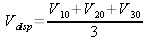 is
used to indicate existence of an earthfault anywhere in the
network (ANSI 59N). The displacement
voltage gives no information about the location of the
earthfault.
The
zero system current, respective ground current ,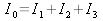 may give information about existence and location (ANSI
51N).
Both
principles may be combined to protect a power network:
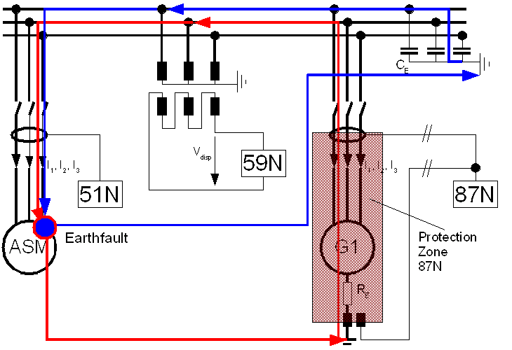
An
earthfault in an insulated network leads to an unsymmetrical voltage
system (U30~0 in our example) and therefore a displacement
voltage
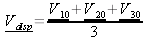 .
So
existence of an earthfault is simply proved (ANSI
59N), the location is not.
The
sum of currents through the phase-to-earth capacitance becomes
different from zero:
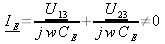
A
current is flowing through the point of earthfault and the cable
capacitance (blue line)
using the ships hull. The zero-sequence current flows through a ZCT
connected to a device with protection function 51N.
So the place of earthfault can be identified by metering the ZCTs
secondary current.
Often
a high-resistance grounding (Resistor RE at generator G1´s
starpoint) is used to improve the power factor at the place of
earthfault. The high-resistance grounding leads to an additional
ground current (red line). This ground
current is flowing through the generator notwithstanding the
earthfaults location. An differential mechanism (87N)
is used to identify inner faults of the generator. This
mechanism is restricted to the protection zone between the current
transformers!
If
network is not designed for permanent operation with an earthfault
(Resistor RE not designed for continous load!!), a
protection scheme must be designed to isolate the fault in three
steps:
The
faulty device should be disconnected by protection function 51N
or 87N with short delay.(e.g. 2 s)
If
the main switchboard can be divided by a tiebreaker, the tiebreaker
should be opened by ANSI 59N, to limit
the earthfaults effects to one one side. (And to limit the blackout
to one side, if step 3 takes effect)
If
the earthfaults location can be not be identified, all working
generators must be disconnected by ANSI
59N to protect the resistor etc.
UH,27.10.04,16:24:04