Blackout Start / Loadmonitor start etc. (Par. 189):
Bit 0:
Some generator sets should be started automatically in case of blackout (Blackout is defined by Umains12 < 10 % rated voltage AND DIO500(2):16 is set by blackout interlock(+24 V) AND generators belonging to the respective subnet neither starting nor connected ).
Blackout start is enabled by setting Bit 0! Start delay is defined in Par. 190!
Bit 1:
Some generator sets should be started automatically in case of insufficient spare power. Loadmonitor start (and stop) may be enabled by setting Bit 1. Spare power limits for start are defined in Par.63 & Par.65 , while spare power limit for loadmonitor stop is given in Par.67. It should be kept in mind, that automatical switch-over between Shaft-Generator/Shore-Connection (SG/SC) is only possible, if Bit 1 is enabled with the generators GPM, while disabled in the SG/SC-GPM!
Bit 2:
Disconnection and stop of generators is blocked in case of insufficient spare power. This applies also in case of disabled PMS/loadmonitor.
To avoid problems with external PMS, this function may be deactivated by setting Bit 2.
Bit 3:
Additional DIO500 mounted for selection of PMS operation modes (Bit 3 set!). That DIO500 may be the third or the fourth DIO, depending on whether an additional DIO is used for step 4 and 5 of Preferential Trip or not (Refer to Parameter104.htm and DIO500.htm)
Bit 4: Preferential TRIP / direct mode
Sometimes it is required to trip unimportant consumers immediately after tripping a generator breaker (without checking, whether the remaining generators are able to take the additional load or not!). If this mode is choosen by making Bit4=1, unimportant consumers will be disconnected by the tripping GPM directly!
Otherwise unimportant consumers will be disconnected not by the tripping GPM but by other GPM. These GPM must become informed about the fact of tripping to reduce their respective tripping delay to (almost) zero.
Bit 5:
Suppression of automatical Unloading
and Stopping by Start Passing Relay (SPR)
If
the GPM500s are only performing the loadsharing without deciding
whether a generator set should be started and stopped, the start
passing signal may processed by an external system only. The internal
functions of the start passing relay can be deactivated by setting
this bit. Not
implemented, deactivate Bit 1
instead!
Bit 6: Tiebreaker Twin configuration
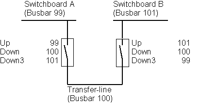
Often two tiebreakers are used to connect switchboards via transfer-line. Each tiebreaker is protecting one end of the line.
Two operation modes are supported:
· If tiebreakers are operated independently, the normal busbar numbering scheme is used.
· If both tiebreakers operating coils are connected and operated jointly, Bit 6 must be set and the busbar No. of the switchboard connected to the other breaker must be placed in Par.91 (Down 3).The following scheme must be used:
That makes sure, that the Tiebreaker-GPM, which gets the START-command, sends frequency-master messages to busbar 99 and 101 and is able to synchronize.
Warning: Using the second option, operating coils of both tiebreakers should be linked in such a way, that the OFF-command may not be affected by any faults in the opposite switchboard. The OFF-Command should also be given on DIO500#1:1 (DI 1) of the opposite twin-tiebreakers GPM500 to avoid a breakerfailure alarm!
Bit 7: Disconnection of unloaded (“EMPTY”) busbars
Generators: Blackout on medium-voltage busbars may allowed if low-voltage mains is fed via shore-connection or from special harbour generator. Therefore disconnection of last generator may be allowed by setting Bit 7, provided that all other consumer breakers (not generator and not tiebreaker) are open. Make sure, that Blackout-Start (refer to Bit 0) is prohibited e.g by linking a “harbour-mode” signal to the blackout interlock!
Tiebreakers: Transfer-lines may disconnected completely, if one of the adjacent tiebreakers is open. Bit 7 allows disconnection of busbars without generator breaker (Busbar 100 in the drawing!).
Bit 8 & Bit 9: Special Function DIO500
Two DIO500 for special functions may be defined by these bits. (Not yet implemented!)
Bit 15: External Power measuring mode
Power signal from AE1 (ZKG500:9, 0-10 V) is used for load sharing and PMS instead of actual power .